Laser Projector
Building a vector-scanning laser projector from junked electronics.
Kevin Mehall, Neal Singer, Adriana Garties, and Avery Louie
At the beginning of the semester, our team came together to do something simple, but difficult. Our goal was to build a laser projector, which is exactly what it sounds like. By controlling the position of a laser, and moving it around fast enough, we hoped to draw vector images. This required building two galvonometers, which, to position the laser accurately, would need to oscillate at fairly high frequencies, to position two mirrors that rotated around orthogonal axes. We also needed precise control loops, since fractions of a degree in the mirror position could translate into inches of displacement in the projected image. Both of these were achieved, allowing us to draw a round circle and variations on the figure eight as test patterns.
Galvo (de)construction
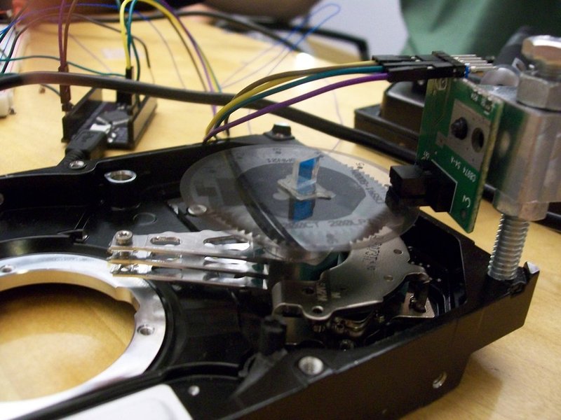
The galvos were made from recycled hard drives. The top of the drives was made out of a single piece of metal attached with screws, which were easily removed (if you try this at home, note that there is often a screw hidden under a label). The platters were removed by unscrewing and removing the bushings that held them on. The power and motor were attached by screws as well. With all the aforementioned parts removed, all that remained was the read/write arm and coil, two very large magnets, and a small PCB attached by ribbon cable, all attached to a large hard drive base. This is essentially a galvanometer.

Encoders
Quadrature encoders/reader pairs were salvaged from old printers. These handy devices allowed us to know what angle the galvo was turned to. Mounts for the readers were made by drilling and tapping holes in the hard drive bases, and then machining brackets that held the readers on delrin rods. These allowed for height, distance, and angle adjustments on the readers. The encoders were mounted to the galvo arms axially, on pieces of scrap aluminum turned down to fit into a groove that already existed on the read/write arm on one side, and turned to fit the encoder on the other side.
Mirrors
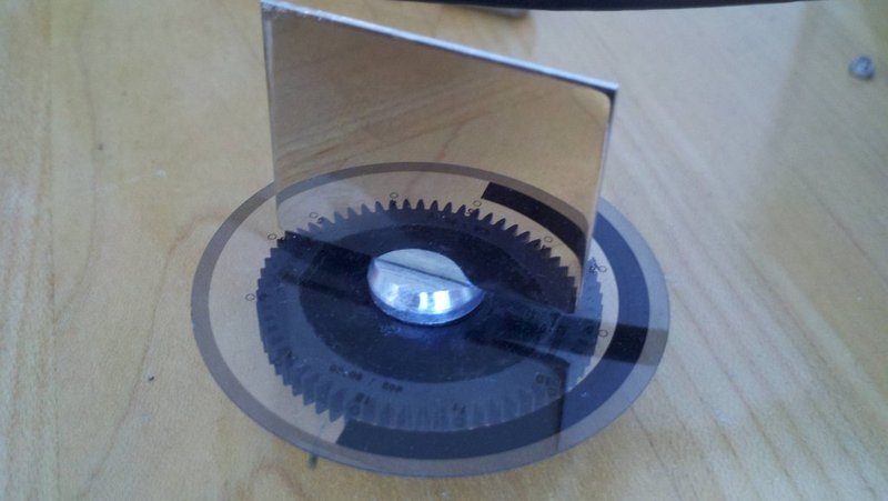
Lightweight first-surface mirrors are required for laser direction. This is because the reflective side of regular mirrors is behind a thick sheet of protective glass, which would cause a double reflection if a laser were aimed at it- one from the glass surface, and one from the mirror surface. Our mirrors were constructed from recovered hard disk platters. These are superior to regular first surface mirrors, because they are are not made of heavy glass. This decreases the moment of inertia of the mirror. The mirrors were mounted using super glue.
Mirror Mounts
Two mounts for the mirrors were turned out of scrap aluminum rod. They both have cylindrical bases that fit into the encoders, and wide bases that allow them to be glued to the top of the encoders. The bases taper to a thin half-round mount for the mirrors. This taper reduces the moment of inertia. The half-round shape was created by filing the original round part flat.
Laser Mount
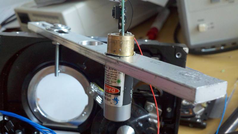
The laser mount was built towards the end of the project. In the recycled, hacked together spirit of the project, it was made out of a piece of scrap aluminum that conveniently had a hole in it. A three-inch long and quartar-inch wide slot was machined out to accommodate a bolt for mounting. Two 9/16-inch holes were drilled to accommodate the laser. This mounting solution allowed a variable radius and angle to mount the laser, allowing us to position it correctly above the mirrors.
Mounting the galvos
With two galvos working, we realized it would be important to make the design adjustable, and easy to take apart and service. One bolt was used to fix the base of one hard drive perpendicular to the other. This allowed for the distance between the two mirrors to be adjusted, while keeping the two axes of the mirrors perpendicular.
H Bridge
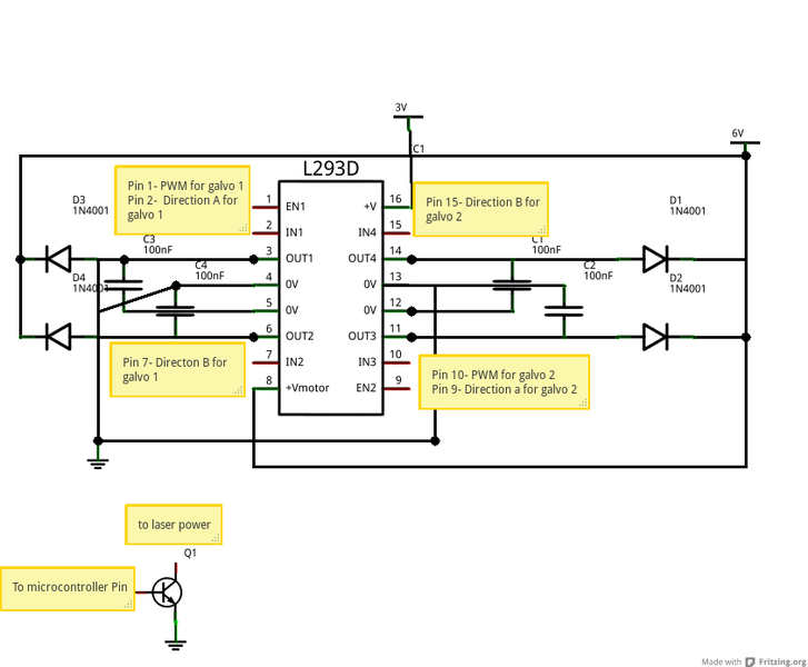
A L293D H bridge was used to power the galvo. This allowed us to drive it in either direction. PWM pulses to the IC let us nudge the the mirrors into just the right position. The bill of material can be found herePower
Since the galvos didn't have any specs, we experimented with how much power we could give them. It turns out we could max out the power rating on our H-bridge at six volts with a power supply current-limited to one amp before we could burn out the coil. Obviously, more power means faster galvo movement, but it also makes it harder to “lock in” to a position in a short amount of time.Laser Control
The original plan for the laser was a complex setup involving three lasers and dichroic mirrors that would combine the lasers into one RGB LASER. However, we spent so much time refining the galvos that it was only practical to use one laser. This was done by bypassing the button on a laser, and then controlling the power supplied to the laser module with a transistor.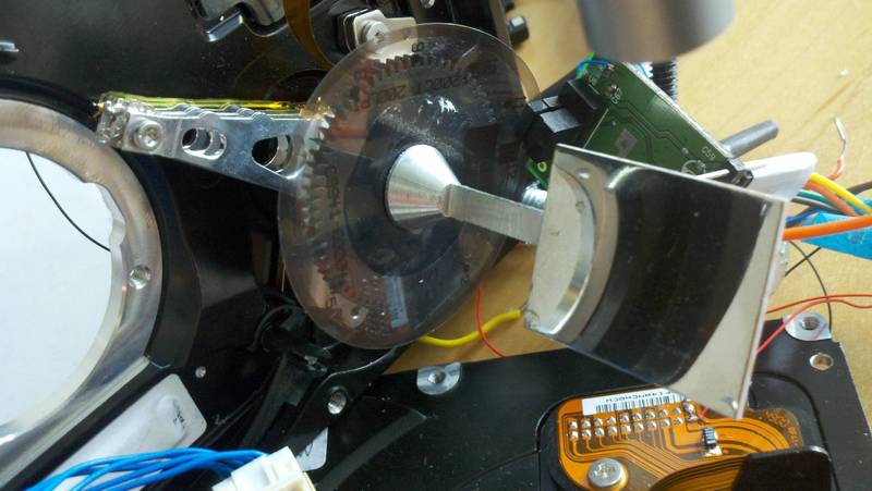
Galvos
The galvos move back and forth based on the direction of the current passed through the coil. The current moving through the electromagnet on the back of the read arm creates a magnetic field that interacts with the magnets embedded in the hard drive. The force created by the arm is proportional to the current. This, combined with the encoders, lets us position the angle of the mirrors.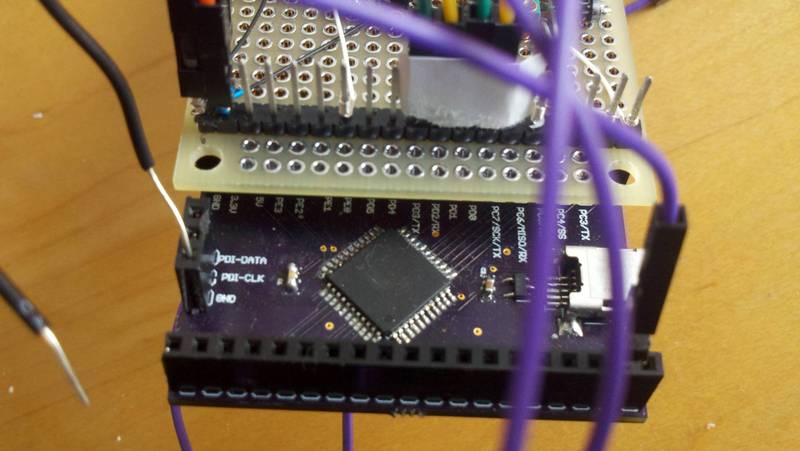
Microcontroller
We used a ATXMEGA32A4U, which is a RISC microcontroller manufactured by Atmel with hardware for USB communication on the chip. This tiny chip was mounted on a breakout/power board designed by our very own Neal Singer.
Firmware
The code for the microcontroller was written in C. It accepts USB control requests over the default endpoint 0 that give it a target position for each of the galvos, or a set of points to go to. It uses built in quadrature-decoder hardware to keep track of the position of the wheel, with an accuracy greater than .05 degrees. The position is fed into the PID control, which returns how much and in what direction to push each of the galvos. This information is used to update the PWM registers. The cycle is repeated 10,000 times a second, moving the laser to a different position fast enough that your brain sees a continuous image being drawn by the laser.
USB
The USB stack on the microcontroller was written by our own Kevin Mehall for Nonolith Labs. It provides a lightweight library for control, bulk, and interrupt endpoints, as well as bootloader support.
Python
We used several Python scripts to connect to the microcontroller via USB and control the laser projector. One simply monitors the encoder positions, and was used to check and align the quadrature sensors. Another uses a series of control transfers to write patterns such as circles, figure 8s, etc. into the point buffer to make the laser projector draw these shapes. We found that results were best if it generated 32 points along the curve.
User interface
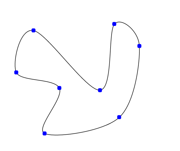
We implemented a web app that allows a user to drag nodes to draw shapes. It constrains the lines to a reasonable approximation of what the projector can actually handle. It sends the list of points to a Python program using the Flask server framework, which passes the list to the microcontroller.
The program worked, but the results were not great. With only a few points, you can draw complex curves that are too fast for the laser projector to handle. It would work better if we added code to interpolate between the points the user draws to keep the laser on the right track.